(DISCLAIMER: Executing these could void the warranty ... I'll have to look into that. - JF)
Also: If you'
don't have any soldering experience, get a friend or technician to help
you.
In this page:
Mute Circuit Adjustment
External Speaker Jack for
112
(bottom)
Accessing the circuit boards on the Transformer
The chassis must be
removed to do this. I don't have a 212 to look at, so I will describe
the procedure for the 112. The 212 should be very similar.
First, lay the amp on
its face. There are two large screws on the top, just behind the handle
and toward the edges (on the tolex, not the plastic corners.) Remove
these. Next remove the power cord restraint clip (inside the cabinet)
and the power cord. Next, remove the three screws that go through the
chassis lip up into the cabinet (above the back panel jacks). You
should now be able to remove the chassis from the cabinet.
NOTE:
Try to avoid touching any big capacitors (cylindrical) near the
power input. They could hold enough charge to pack a nice wallop.
Place the chassis on a
workbench or table with the knobs facing you.
The Transformer's mute
circuit is
designed
to cut the preamp signal if the line voltage drops below a certain
threshold. The stock amp will start cutting signal around 112 VAC,
which is too high. I've had volume drops (similar to a hard tremolo)
when the line voltage drops due to long extension cords shared with PA
or bass, etc. No problems since making the mod.
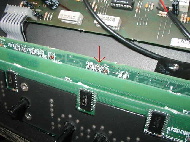
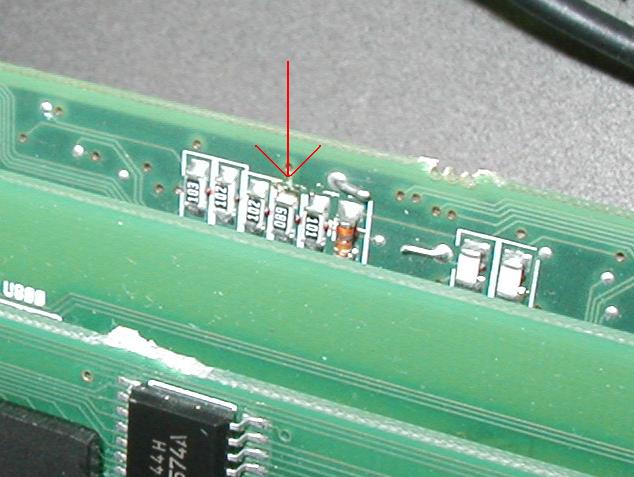
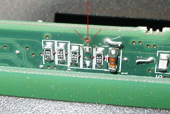
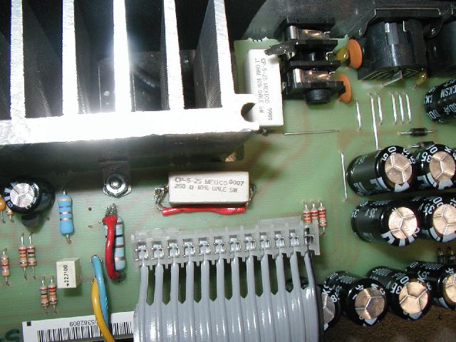
The modification
involves removing a single surface mount resistor (68-ohm, labeled
"680"), thereby lowering the mute threshold to around 102 VAC. It
resides on the main preamp board - roughly behind the pre gain knob.
Use the following
pictures as a guide:
|
|
|
| Before |
Before
(zoomed) |
After
(zoomed) |
 |
 |
 |
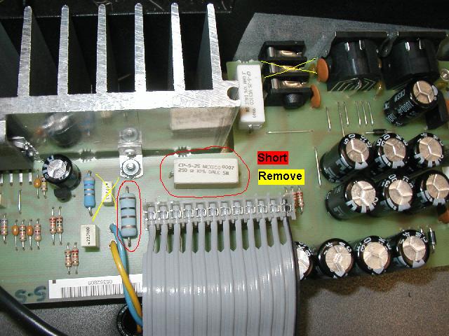
| Before |
Jack
mod |
After |